In this part, we will implement multisampling to our ray tracer. We hope that we can reduce aliasing artifacts which caused by not having enough samples for the world that we are trying to capture. After that we will discover some techniques which takes advantage of the multisampling without adding too much computational cost.
Multisampling
For the multisampling, we just need to sample multiple times from each pixel point and take the average of the colors. To do so without changing our code so much, we can just create two random floats for each sample and than we can use it to offfset our u and v values which are the floating point coordinates of the screen space.
To sample uniform random numbers, we can use the following code which is Merseene Twister random number generator implemented in C++ standard library.
inline std::mt19937 gen;
inline std::uniform_real_distribution<float> dis(0.0f, 1.0f);

inline float frandom()
{
	return dis(gen);
}
At first, I placed the generator objects in the random function which caused the generator to be reinitialized every time the function is called. This caused the random numbers to be the same for each sample. To fix this, I placed the generator objects outside as persistent objects for each call to the function.
After that I added the following code to sample random points for each pixel.
auto sample_u_offset = frandom();
auto sample_v_offset = frandom();
const auto u = (i + sample_u_offset) / (float)(imageWidth);
const auto v = (j + sample_v_offset) / (float)(imageHeight);
For constructing the final color, we just need to average the colors of the samples. To do so, we can just add the colors of the samples and divide it by the number of samples.
Just with the multisampling we can see the difference in the final image. The aliasing artifacts in the edges are significantly reduced with bigger number of samples.

Difference can be seen in the edges ot the objects
Depth of Field
To achieve the depth of field effect, we need to simulate the camera lens. To do so we can think of an imaginary lens between our image plane and a focal plane (the plane where the objects are in focus). After that we can pick random points from lens and after that we can send rays from that point to the focal plane. This way for every sample, if the ray hits some triangle near the focal plane it won’t be blurred, but if as the ray goes further from the focal plane, the image will be blurred.
The following code snippet shows how we can achieve this effect. Two random points picked, as imagining the lens as a square will help us to sample uniformly.
ray getRay(float se, float te) const
{
  if(!dof_enabled)
    return ray(origin,  lowerLeftCorner + se * horizontal + te * vertical - origin);

  auto q = lowerLeftCorner + se * horizontal + te * vertical;
  auto s = origin + (aperture * u * lens_x_offset) + (aperture * v * lens_y_offset);
  auto direction = unit(origin - q);

  auto tfd = focusDistance / dot(direction, -w);
  ray r(origin, direction);
  auto p = r.at(tfd);
  auto d = p - s;

  return ray(s, d);
}
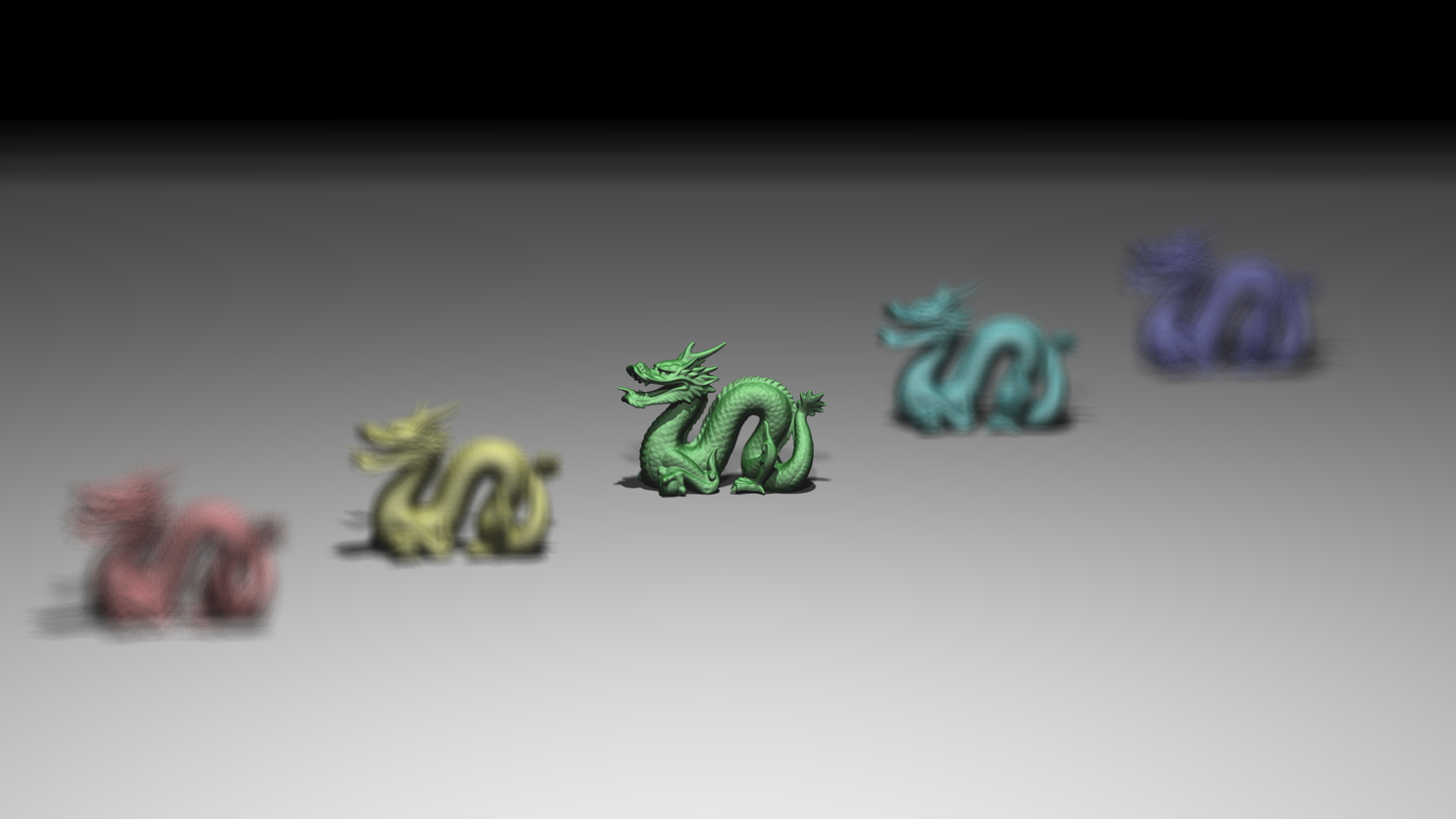
Dragon models with Depth Of Field effect
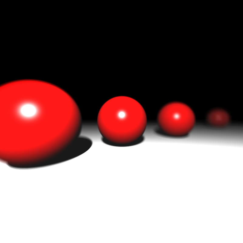
Spheres with Depth Of Field effect
Motion Blur
To achieve the motion blur, we need to move our objects in a way that they will be in different positions in different samples. To do so we can just use a motion vector, and for each sample we can move the objects according to this vector multiplied with a random float. At my first implementation I used a different random point each time a object’s model matrix is used, however this lead to wrong intersection and bounding box calculations for the BVH. To fix this, I used the same random point for each sample, and it fixed my problem.
if(object->has_motion_blur)
{
  vec3 random_motion = object->motion * motion_blur_mp;
  mat4 translation = mat4::translate(random_motion.x(), random_motion.y(), random_motion.z());
  model = translation * object->model;
}
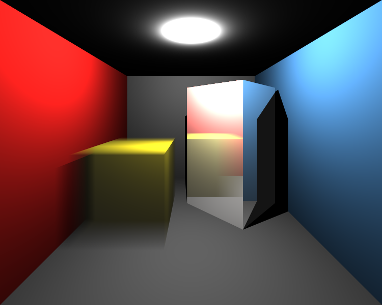
Cornellbox with motion blur effect
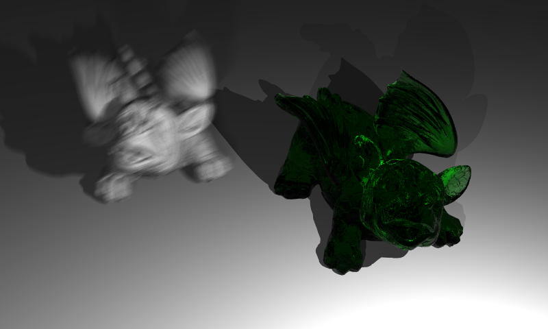
Dragons with motion blur effect
Glossy surfaces
To achieve the effect of glossiness, we can use a roughness value for mirror, dielectric and conductor materials. And for each material we can divert the reflected ray from the surface normal by a random angle. This requires us defining a local coordinate system for our reflected rays. After that we can use two random points and roughness value to multiply the new axis vectors of the local system.
We can use the following code to achieve this effect.
if(has_roughness)
{

  auto r = unit(reflected);
  auto rp = create_non_colinear_vector(r);
  auto u = unit(cross(r, rp));
  auto v = unit(cross(r, u));

  auto rr = unit(r + u * roughness * ((frandom() - 0.5f) * 1.0f) + v * roughness * ((frandom() - 0.5f) * 1.0f));
  return ray(rec.p, rr);
}
To create a non colinear vector, we can set the absolute minimum component of the vector to 1.0. This can be achieved in different manners however for now this will be sufficient.
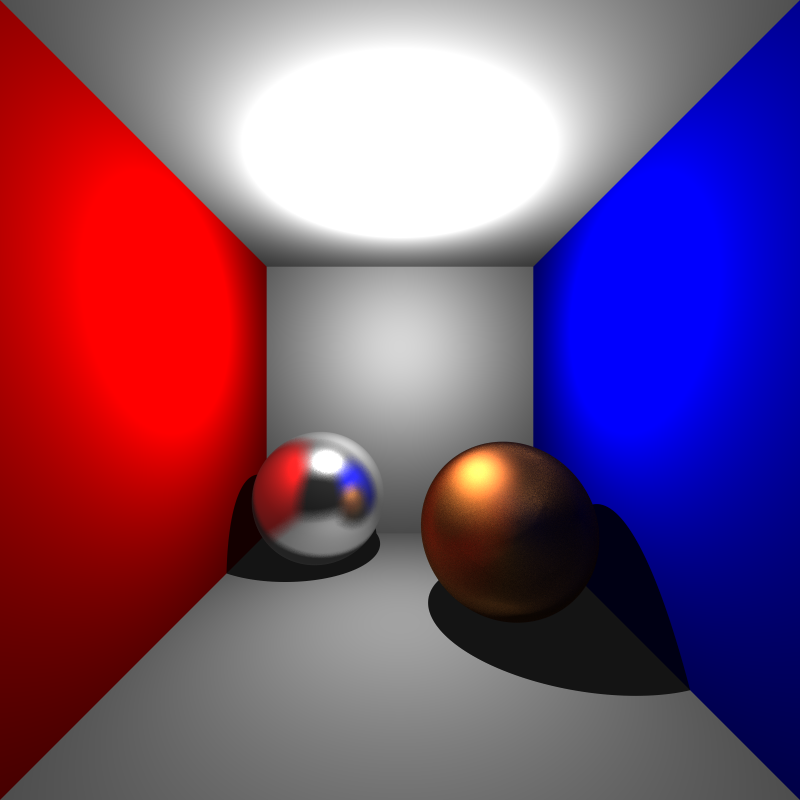
Cornellbox with glossy surfaces
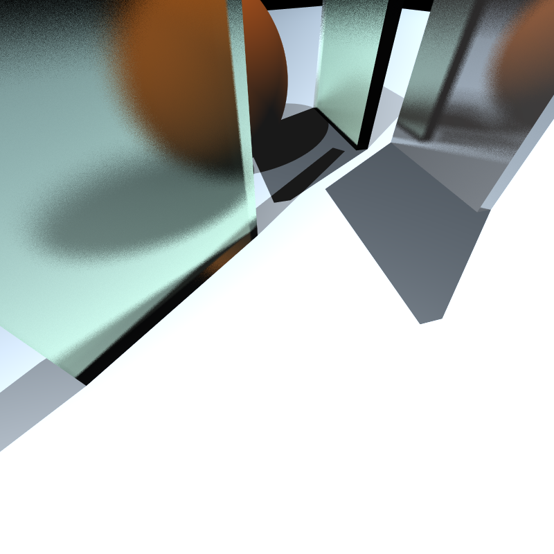
Rough metal surface and blurry glasses
Area Lights
To achieve area lights, we can sample a random point for our light area and adjust the formula to approximate the irradiance. To sample a random point in the light area, we can just use the same logic as we used in the glossy surfaces, we can define a local coordinate system from the normal vector of our plane which defines an area light. After that we can use two random points to sample a point in the light area which will be limited by the size of the edges of our area light. To add area lights without changing our material code we can define a base lighting interface which will be implemented by the area and point light classes. Which will only need to have get_position and get_intensity functions.
point3 area_light::get_position() const override
{
//create a basis and sample a position
vec3 np = create_non_colinear_vector(normal);
vec3 u = unit(cross(normal, np));
vec3 v = unit(cross(normal, u));
float u_offset = (- size / 2.0f) + (size)*area_light_u_offset;
float v_offset = (- size / 2.0f) + (size)*area_light_v_offset;
return position + u * u_offset + v * v_offset;
}
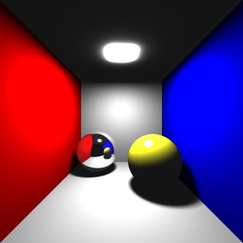
Cornellbox with area lights
Problems with Camera
In one of the cornellbox scenes, I noticed a bug in my camera implementation. The bug was caused by the fact that I was intersecting the objects before the image plane which caused only a plane to be visible in the scene. To fix this, I just used a minimum t value for the intersection tests which is the distance to the sample in the image plane from the camera origin. After that I noticed a different bug that caused from non symmetrical image plane boundary volumes. In my implementation to calculate the lower left corner of the image plane I was moving the center position by the half of the horizontal and vertical vectors which I was calculated with difference in near plane boundaries and the camera vectors. I fixed this problem by moving the center position by the respected boundary value of the image plane.
Updated camera code is as follows.
camera(point3 lookfrom,
      point3 lookat,
      vec3 vup,
      parser::Vec4f near_plane,
    bool _dof_enabled,
      float _aperture,
      float _focusDistance,
      float nearDist)
{
  w = unit(lookfrom - lookat);
  u = unit(cross(vup, w));
  v = cross(w, u);

  origin = lookfrom;
  horizontal = (near_plane.y - near_plane.x) * u;
  vertical = (near_plane.w - near_plane.z) * v;
  lowerLeftCorner = origin - (unit(horizontal) * fabs(near_plane.x)) - (unit(vertical) * fabs(near_plane.z)) - nearDist * w;

  dof_enabled = _dof_enabled;
  aperture = _aperture;
  focusDistance = _focusDistance;
}
Problem with Linux Build
I use windows as my main operating system for C++ development with CMake and Visual Studio, and when I tested my code on linux, I noticed some strange bugs like black images or negated colors on some examples. After a heavy debug session I noticed some different compiler behaviour between MSVC and GCC. The problem was caused by my usage of the abs() function which is defined in the cmath library. The problem was caused by the fact that the abs() function is defined for integer types in the cmath library, and for floating point types it is handled correctly for MSVC but not for GCC. To fix this problem I just used the fabs() function which is defined for floating point types in the cmath library.
Bonus Video
References
Ahmet Oğuz Akyüz, Lecture Slides from CENG795 Advanced Ray Tracing, Middle East Technical University