In this project, as a team of two people, we decided to reimplement the dynamic cubemap application using Vulkan. The previous implementation was using OpenGL. In this text, we are (1) reimplementing the dynamic cubemap application, then (2) comparing between the two implementations, in terms of metrics such as FPS.
What is OpenGL?
OpenGL is a cross-platform rendering API (started development in 1991, released in 1992) for vector graphics, maintained by Khronos Group. Being cross-platform makes it advantageous over its alternatives such as D3D (Direct3D) which was designed by Microsoft specifically for Windows. It’s an older API.
What is Vulkan?
Vulkan is also a cross-platform rendering API for vector graphics, maintained by Khronos Group. OpenGL’s performance and efficiency was rivaling API’s such as Microsoft’s D3D 11. With the arrival of D3D 12, and Apple’s Metal APIs, the demands of graphics industry exceeded what OpenGL had to offer. Therefore, Vulkan was announced in 2015 and released in 2018, being a low-head API stepping into the competition. OpenGL uses a single state-machine, which means that every host instruction is sequential, making it less feasible to run on multiple threads. However, Vulkan uses objects instead, allowing for multi-thread support. It also has multi-GPU support. OpenGL also it as long as both devices are the same model (SLI for NVIDIA and Crossfire for AMD). Vulkan allows for devices with different models. Being cross-platform also makes it advantageous over its alternatives such as D3D and Metal.
Preliminary
Environment Mapping
Environment mapping is a type of texture mapping that incorporates sampling a texel from an external texture and approximating it on an object surface. The object may have reflective or refractive properties depending on the image texture. There are a variety ways of doing this, such as sphere mapping and cube mapping. We will use the cube mapping.
Cube mapping
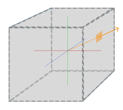
Cube mapping is a type of environment mapping that uses essentially a cube of 6 planes (called a cube map), each having a texture. A normalized direction vector is calculated from the origin of a cube object and the with the aid of this vector, the properties of the fragment intersecting the vector is sampled from the image texture. A picture illustrating this concept is below
Cube maps has basically two types. When textures are provided from an image texture, it is called static cube mapping. However, static cube maps are not much useful in real-time applications. The other type is called dynamic cubemaps, which is used to render a scene into the sides of a cube. It can be used to create reflections as we will implement in this project.
Contents of the Project
In this project we will create a fixed skybox object with static cubemaps and create a mirror object which uses a dynamic cubemap to reflect the scene. In the scene there will be one floating object with different polygon counts to compare the results between Vulkan and OpenGL. To debug the scenes, user can fly around the scene using the keyboard and mouse.
Explanation of the Shaders
Vertex shader for skybox is below.
            #version 460 core
            layout (location = 0) in vec3 aPos;

            out vec3 texCoords;

            uniform mat4 projection;
            uniform mat4 view;

            void main()
            {
                texCoords = aPos;
                vec4 pos = projection * view * vec4(aPos, 1.0);
                gl_Position = pos.xyww;
            }
We feed the coordinates of the vertices as aPos variable. We don’t need a model matrix since we will not do additional transformations to the skybox such as rotation, scaling and translation. In order that the rendered scene in the viewport changes as the user inputs, we need view and projection matrices.
In the previous implementation, the line gl_Position = pos.xyww;was gl_Position = pos and we were rendering the skybox object first. The scene objects were written on the skybox. This was working however was inefficient, due to the fact that we were rendering every fragment of the skybox. When user was moving in the scene, there could be cases where a scene object was (almost) completely blocking the skybox. For such cases, we render the skybox last. In order to compensate for this we made both the z and w components the same. Because we are using the perspective projection, we have a perspective divide, making both z and w components 1. Because z is the largest value, which is 1, no matter when the skybox was rendered, it would (almost) always fail the depth test. To remove almost we change the depth test so that the depth value with less than or equal to the current depth value passes. After the skybox, we may revert back to the default which was to pass the depth values less than the current.
Fragment shader for skybox is below.
  #version 460 core
            in vec3 texCoords;

            out vec4 FragColor;

            uniform samplerCube skybox;

            void main()
            {
                FragColor = texture(skybox, texCoords);
            }
Notice that the texture coordinates are 3D coordinates as we are using a cube map (Notice the variable with samplerCube field). Further note that the they are the interpolated from the coordinates fed by the vertex shader. We are simply sampling the fragment color, similar to any texture.
Note that both vertex and fragment shaders of the mirror are used for scene objects. Vertex shader for the mirror is below.
#version 460 core
            layout (location = 0) in vec3 aPos;
            layout (location = 1) in vec4 aColor;
            layout (location = 2) in vec3 aNormal;
            layout (location = 3) in vec2 aTexCoords;

            out vec3 pos;
            out vec4 color;
            out vec3 normal;
            out vec2 texCoords;

            uniform mat4 model;
            uniform mat4 view;
            uniform mat4 projection;

            void main()
            {
                pos = vec3(model * vec4(aPos, 1.0));
                color = aColor;
                normal = mat3(transpose(inverse(model))) * aNormal;
                texCoords = aTexCoords;
                gl_Position = projection * view * vec4(pos, 1.0);
            }
Because we are using this shader on scene objects, we may use the model matrix this time. We are given positions, colors, normals and texture coordinates in aPos, aColor, aNormal and aTexCoord. Whenever user moves, we need to update the viewport. We set gl_Position accordingly. However, position and normals need to be updated differently, because normals’ w component is 0, not 1.
Fragment shader for the mirror is below.
#version 460 core

            in vec3 pos;
            in vec4 color;
            in vec3 normal;
            in vec2 texCoords;

            out vec4 FragColor;

            uniform vec3 cameraPos;
            uniform samplerCube skybox;

            void main()
            {
                vec3 I = normalize(pos - cameraPos);
                vec3 R = reflect(I, normalize(normal));
                FragColor = vec4(texture(skybox, R).rgb, 1.0);
            }
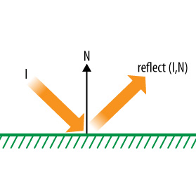
We are computing the eye (I) and direction (R) vectors. We are similarly sampling with the direction vector. Notice the similarity to the skybox’s fragment shader. The difference is that we may also use this shader with dynamic cube maps.
OpenGL Implementation
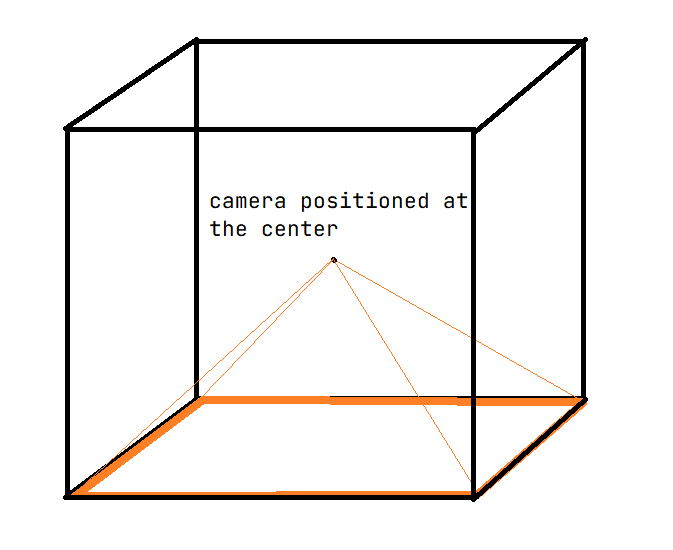
First we need to create a framebuffer, they are usefull for rendering off-screen just like in our case. Then, we set our camera’s position into the objects position whose surface is reflective. After that it is simple, we render 6 times with 90 degrees viewing angle in each direction for our cube’s faces and move these into our cubemap texture. While doing this we need to make sure that our reflective object is not in the scene to get the result without the inside of our object.
All there is left to do is sampling from the cubemap texture in our fragment shader of our object with a function called “reflect” which calculates the reflection of the direction between our camera and our point with a given surface normal.
A scene with a reflective teapot and orbiting objects. We can see that the reflections are crystal clear.
Creating these framebuffers and rendering them into a texture is a breeze. The reason behind that is in OpenGL most of the things are set to default if you don’t change them. This helps to creating basic applications like this in a faster way.
Vulkan Implementation
In the core of the things, we did the same in the Vulkan. We created a framebuffer, we set it to offscreen, we created a cubemap texture to copy the offscreen renders. Also, the shaders are same as the OpenGL. We write the shaders in GLSL and compiled them into SPIR-V.
However, in each step the lines of codes are multiplied against the OpenGL. For example, to render different objects with two different shaders, we need to create two different Graphics Pipeline objects in which we specify all of the steps of a graphics pipeline like viewport, culling, shader steps, shader layout informations, the vertex buffer informations, rasterizer information, multisampling information, stencil informations, color formations. After specifying these things, we collect them and create the pipeline for each object with different shaders.
VkGraphicsPipelineCreateInfo pipelineInfo{};
        pipelineInfo.sType = VK_STRUCTURE_TYPE_GRAPHICS_PIPELINE_CREATE_INFO;
        pipelineInfo.stageCount = 2;
        pipelineInfo.pStages = shaderStages;
        pipelineInfo.pVertexInputState = &vertexInputInfo;
        pipelineInfo.pInputAssemblyState = &inputAssembly;
        pipelineInfo.pViewportState = &viewportState;
        pipelineInfo.pRasterizationState = &rasterizer;
        pipelineInfo.pMultisampleState = &multisampling;
        pipelineInfo.pDepthStencilState = &depthStencil;
        pipelineInfo.pColorBlendState = &colorBlending;
        pipelineInfo.layout = pipelineLayout;
        pipelineInfo.renderPass = renderPass;
        pipelineInfo.subpass = 0;
        pipelineInfo.basePipelineHandle = VK_NULL_HANDLE;

        if (vkCreateGraphicsPipelines(device, VK_NULL_HANDLE, 1, &pipelineInfo, nullptr, &graphicsPipeline) != VK_SUCCESS) {
            throw std::runtime_error("failed to create graphics pipeline!");
        }
After feeding all the information Vulkan needs, one difference is the drawing commands into the GPU. In Vulkan there is a concept called Command Buffers which you can prerecord your GPU calls and after that you will never be overheaded with the draw commands. However, while creating our code while rendering into the dynamic cubemap, we need to change the view matrix in the shaders. We couldn’t write the code for prerecording these commands, and in the end in each frame we rerecorded these commands then submit them into our GPU.
And while writing these codes, there is a need to create a validation layer in Vulkan to debug the program. In default most of the Vulkan commands will take structures as parameters and it doesn’t check the inside of these structs. This will cause problems like if you send a wrong command, the program will most likely crash. To prevent this while debugging we activated these validation layers to check these parameters and some other stuff and throw us the error codes that we need to solve.
Other than the sheer amount of information we need to pass into Vulkan, we couldn’t make the code into a clean structure. The reason behind this is while writing the code we didn’t know what we need in the end. This forced our code into being a big complicated pile. We think that our code is far from optimized.
Here is the end result of the dynamic cubemap application in Vulkan.
Comparison and Benchmarking
In this section we compared these programs with respect to the performace.
Metrics Used
We compared the average frame time in ms in order to see the performance of the programs. We didn’t use the FPS because we thought that using the frame creation time is a more intuitive metric. The lower times will be better with respect to the performance because it creates the frames faster.
We found three models with different triangle counts, a cube with 24 triangles, a teapot with 2.3k triangles, and a hover with 480k triangles.
Results
Cube Model
Here is the videos of the two programs with cube model (24 Triangles).
Above is the Vulkan Implementation.
Above is the OpenGL Implementation.
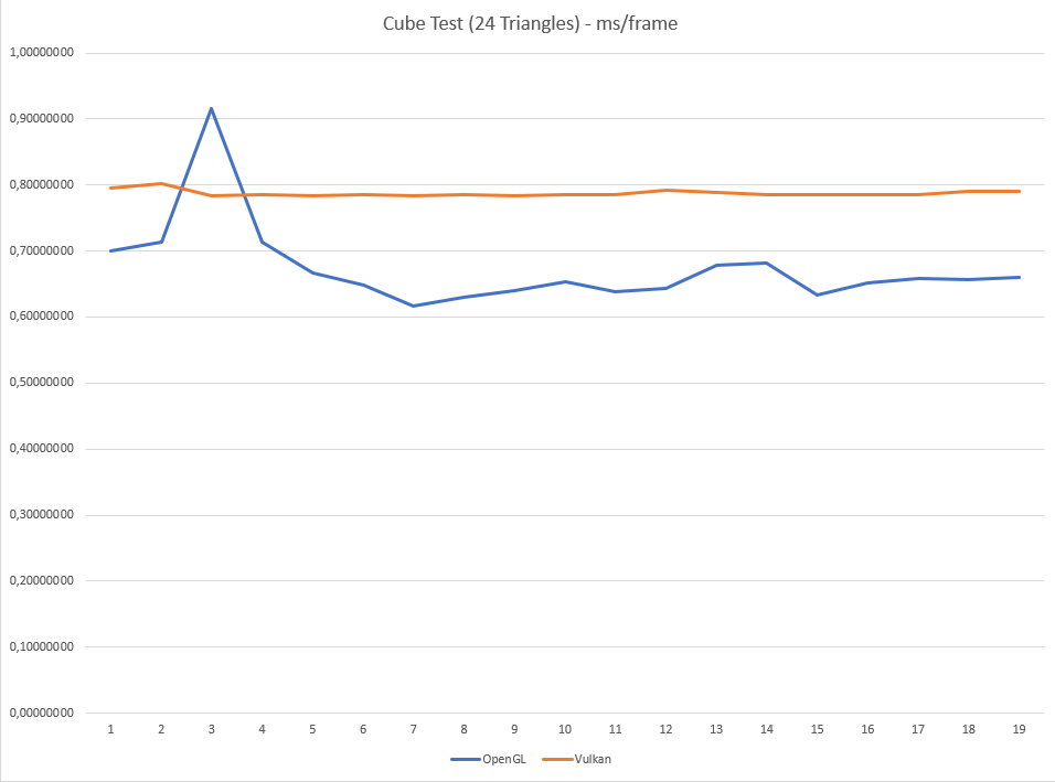
The results show that, in the scene with the cube models, OpenGL is faster.
The reason behind this is may be our code in the Vulkan. For example, if we were able to prerecord the draw commands, I believe that the Vulkan’s speed will be much faster.
Teapot Model
Here is the videos of the two programs with teapot model (2.3k Triangles).
Above is the Vulkan Implementation.
Above is the OpenGL Implementation.
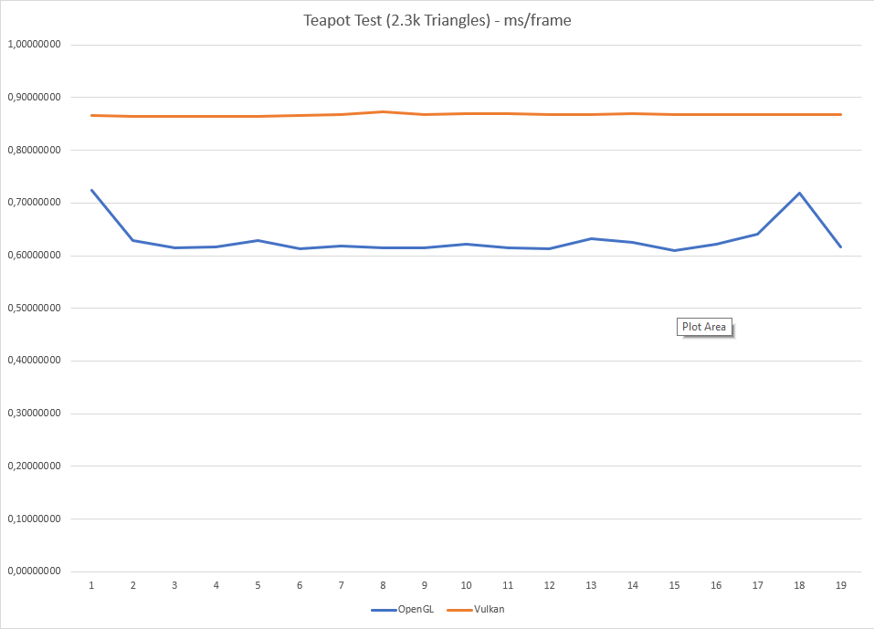
The results show that, in the scene with the teapot models, OpenGL is still faster. However, the difference is slowly decreasing
With these two tests, we can see that spikes and other fluactiations doesn’t occur in Vulkan. This is also an important thing, becuase in graphics applications little changes in the FPS will be appearent.
Hover Model
Here is the videos of the two programs with hover model (480k Triangles).
Above is the Vulkan Implementation.
Above is the OpenGL Implementation.
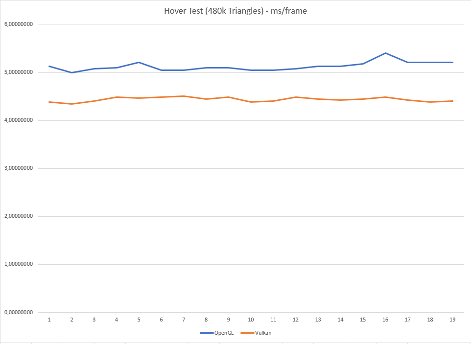
With the increased number of polygons we can see that Vulkan is performing better than OpenGL.
The reason behind this is may be the Vulkan has some fixed time to get the necessary information and create objects but it is efficient when drawing higher number of polygons.
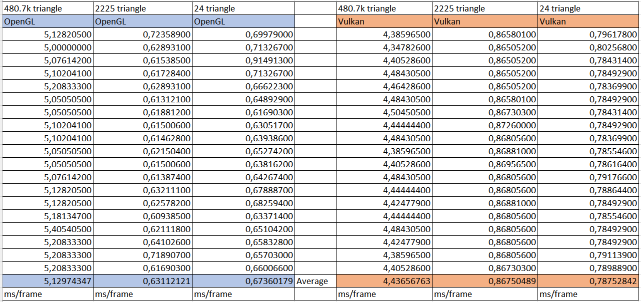
All the data we collected from these 3 different scenes.
Conclusion
We saw that creating basic graphic applications in Vulkan is very different than OpenGL in the details. In the both API the core of the things are the same, however internal details is much more appearent in the Vulkan. In the Vulkan, you can feel that you are very close to the GPU. This means if you know what are you doing, you can write optimized codes for spesific purposes. In our scenario, after learning OpenGL, Vulkan made us learn the finer details in the pipeline of a graphics application.
In the end, we saw that even with our un-optimized code, Vulkan is faster that OpenGL in high polygon counts. However, with low polygon count OpenGL’s speed can help when creating a prototype with the addition of the rather more understandable codes.
References
Overvoorde, A. (n.d.). Introduction. Introduction - Vulkan Tutorial. Retrieved July 7, 2022, from https://vulkan-tutorial.com/
Hongtongsak, K. (2020, July 6). Dynamic-Cubemaps. Retrieved July 1, 2022, from https://khongton.github.io/Dynamic-Cubemaps/
Wikimedia Foundation. (2022, March 12). Reflection mapping. Wikipedia. Retrieved July 1, 2022, from https://en.wikipedia.org/wiki/Reflection_mapping#Cube_mapping
Wikimedia Foundation. (2022, June 8). OpenGL. Wikipedia. Retrieved July 1, 2022, from https://en.wikipedia.org/wiki/OpenGL
Wikimedia Foundation. (2022, June 26). Vulkan. Wikipedia. Retrieved July 1, 2022, from https://en.wikipedia.org/wiki/Vulkan