In this project, the aim is to create a surface from scratch with bezier curve equations. This will allow us to create animations simply by changing the control points of the surface we want to create. I will do the computations on the CPU and then send the mesh to the GPU with a texture, so this process is not optimal by any means. I used OpenGL 4.6 to implement the project.
Idea behind the bezier curves and surfaces
In the Computer Graphics field to mimic nature, we need some functionality to represent smooth shapes. There are many algorithms to do it, but they need to have some properties to be useful. They need to be fast to compute and can be easily designed to model various things.
A good and balanced way is to use cubic polynomials. Many different uses of these polynomials by their constraints lead to different kinds of curves. The most known versions are Bezier curves, Hermite curves, and splines. The main focus of this project will be Bezier curves.
Bezier curves are defined with 4 points, the first and the last one are the start and endpoints of our curve. The intermediate ones are for the direction of the curve in-between steps. With these points and linearly interpolating multiple lines, we will have our Bezier curve. The curve is defined in the convex hull of these control points. This property can help us in some applications like robotics, or game development where we need to estimate the boundaries of our path without calculating the whole curve.
Interpolation of the Bezier curve.
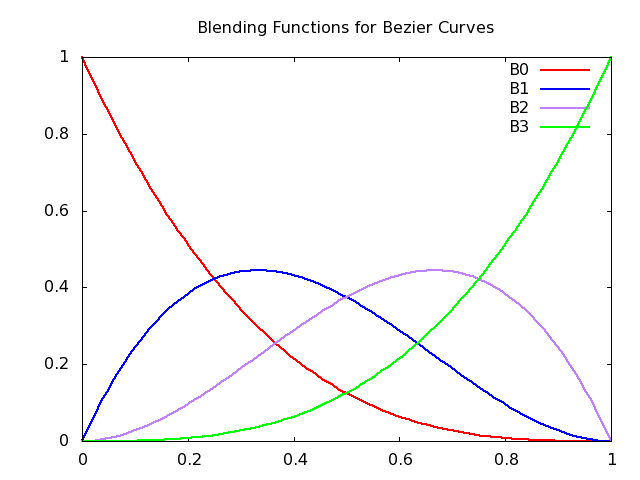
Blending function of Bezier curves which shows the effect of the control points through the curve.
How to create a bezier surface
We had our curve in our hands, to make it a surface we need to add a new dimension to the curve. If we define the control points of our curve as other Bezier curves, if we sample these infinite curve clusters with a wanted rate we will have a point cloud that represents a surface.
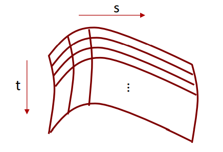
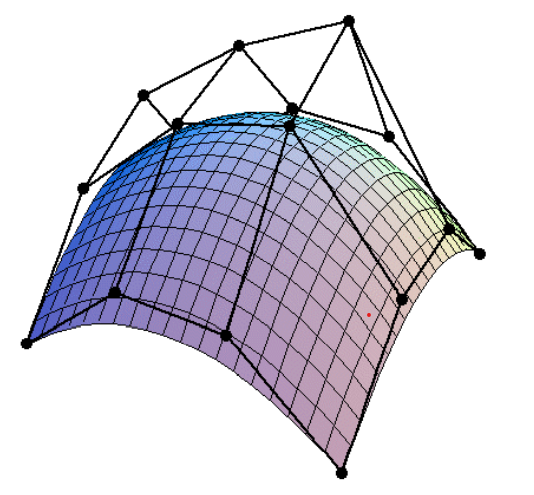
In a way, we have 4 curves in each direction that spawn from the control points of the curve. This means with a total of 16 points, we can define a bezier surface that can be easily adjustable for our needs.
I started my implementation by defining these surface equations as matrix calculations. With these matrices, we can easily sample our points in wanted intervals. I created three different matrices for each dimension (x,y,z) with 16 different control points. After that, I defined the Bezier curves base matrix which comes from the wanted control points interpolation in polynomials. Then with the following equations, we can sample our points through the two directions in which we created our curves on in the interval u x w = [0,1]x[0,1].
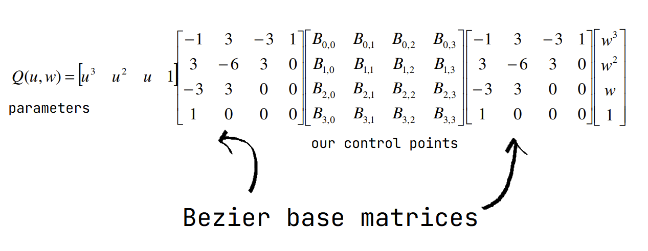
Equations for the bezier curve with matrices.
After creating matrices, I simply iterated with wanted sample counts, and I weave them as triangles. I used a basic normal calculation in vertices which averages the neighbor faces normals in the end.
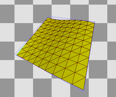
My first implementation with 10 sample points.
How to create patches with G1 continuity
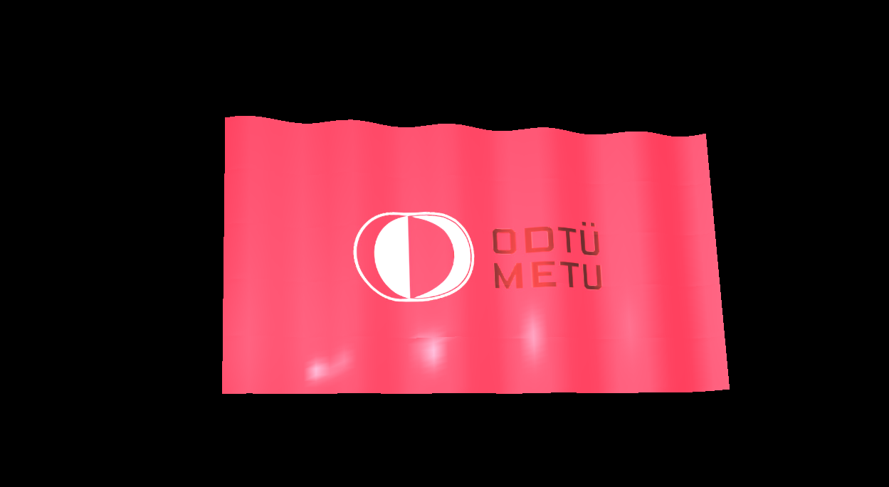
We now have a dull surface. We can add some patches and animate the surface to shake things up. The animation part is easy because we can easily change the control points. However, the 16 control paints may not be suitable for someone’s needs. To increase our control points, we can implement the same with more than 1 Bezier surface equation, namely patches. And finally, I added some texture to it to mimic a flag waving in windy weather.
We want some continuity with the surface, no one wants a surface with holes on it. The concept is easy on the core level. For the first level of continuity, we need to merge the control points of the borders. Where one surface ends, the other one should start.
We can do more than just connect control points. In the context of the curves, the next level is keeping the same tangent on both ends, but on surfaces, we can ease this down a bit. We can be sure to have the control points before the edge, on the edge, and after the edge in the next patch on the same line. This continuity is called G1 continuity. This will help us to have a smoother surface. This one is already ensured if we create a surface with all control points on the same plane. However, we want to animate this surface so this can move the control points out of the plane.
To solve this issue, I animated the control points in a way that the G1 continuity is preserved. I created my patches on the x-y plane and if I move one control point before the edge on the z axis, I move the control point after the edge by the inversed amount. This ensures that the slope before and after an edge is the same.
A surface constructed from multiple patches.
In this picture, you can immediately notice that there are artifacts present on the edges between patches. We will inspect this problem in the following sections.
Debugging an OpenGL program with RenderDoc
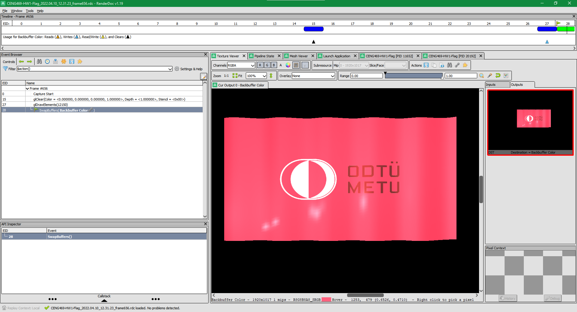
Before moving on to the artifact problem, I want to talk about a program I found to debug graphical programs which use OpenGL, DirectX, or Vulkan. The name of the application is RenderDoc. In it you can view different meshes that are rendered in a scene, you can see the events that happened through the rendering process and you can get important information about shaders, or even decompile them.
You launch an application with the application and then you capture the frames you wanted to inspect.
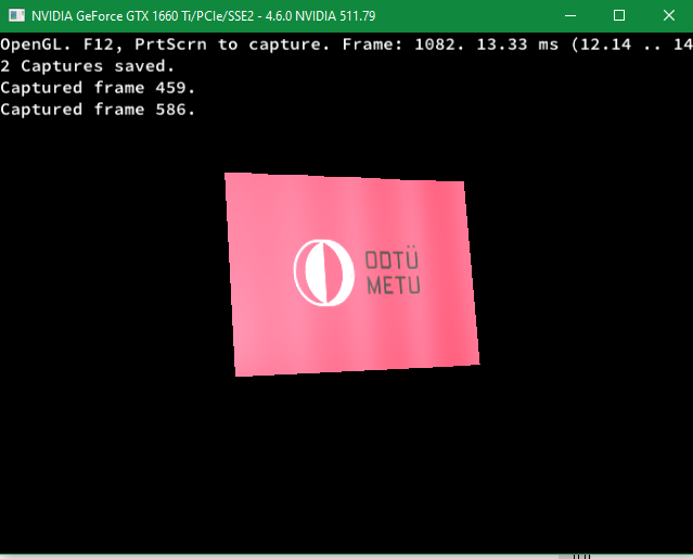
Capturing frames from our application.
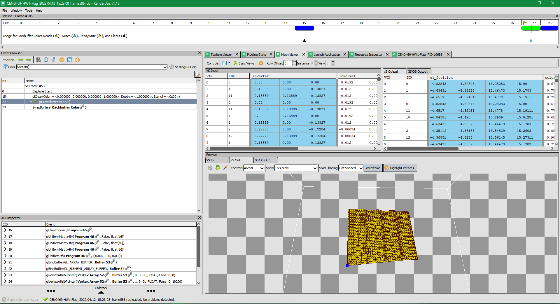
Mesh viewer interface of the RenderDoc.
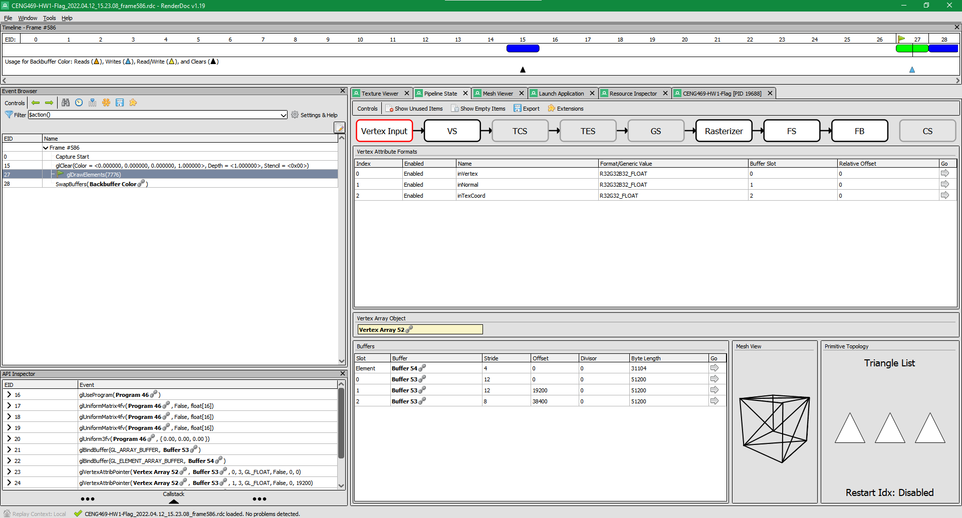
Shader pipeline viewer of the RenderDoc.
The shader information helped me in this assignment to solve a problem while loading the textures. And viewing my triangles.
The problem of normals
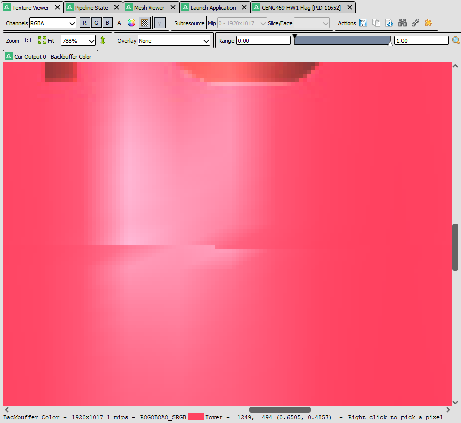
The zoomed version of our problem.
In this problem, I first thought the reason is because of some problems with intersecting triangles because I loaded edge vertices more than once. The reason behind this is I created each patch independently. However, In the RenderDoc’s mesh viewer I saw that the triangles seem fine.
The next possible cause is the calculation of the normals. In my normal calculation, I also calculate them for each patch. I found out that my averaging method is the problem. In the edge vertices, normals will curve towards the left or right because the triangle count is not equal on each side. This is not a problem in the other vertices because the symmetry of the triangles cancels out each other.
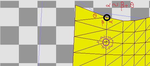
The angles of the vertices showing our problem.
There are many ways to solve this problem, in the example, we can calculate the normals after we created all the patches. However, this solution requires changing the main loop and adds complexity to the index calculations. We can solve this more intuitively, we can weigh each triangle’s contribution to the normals with their angle on the wanted vertex. This will solve the directions of the normals on the edges.
The edge artifacts disappeared.
Rotating our surface
Finally, we have a flag that animates smoothly. However, to find the best angle for the best look we may need to rotate our flag a bit. To change the angle interactively, I implemented a mouse callback that rotates our flag according to a vector that is perpendicular to our mouse’s direction vector. It uses quaternions to calculate the rotations before each draw call. In my future projects, I want to work more on the quaternions.
Rotating our surface with mouse.
Final words and future work
We have a good-looking flag that can rotate. This project is fun to implement. In the future, I wanted to work more on creating classes in C++ to handle scenes with multiple meshes in a more organized way.
References
Ahmet Oğuz Akyüz, Lecture Slides from CENG469 Computer Graphics II, Middle East Technical University